WaterTribe Rudder Contender
A Kayak Rudder Conversion
By Larry Miller (aka PaddleFoot)
Does a WaterTribe Rudder already exist? Scanning through the
WaterTribe Rudder
Discussion Forum, I see that most of the requirements mentioned are
met by the rudder I
designed and built five years ago. Having built two more since then,
the design is now
fairly refined. Were I to build another, there is little I would
change, unless to try a foiled
blade or eliminate a few more ounces of weight. Although I designed
this rudder to give
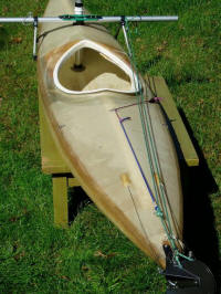
an old pointy-ended river kayak a new life as a sailboat, it could
be adapted to most
kayaks.
|
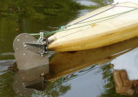
A flat-blade, hard-anodized
aluminum rudder for sailing |
When I ordered my first Balogh Sail Designs sail and BOSS rig,
Mark Balogh
recommended a commercially available kayak rudder and provided a
template for a
balanced blade suitable for sailing. After considering the
modifications necessary to adapt
the commercial rudder to my 20-year-old fiberglass Phoenix Cascade,
and the need to cut
a new blade, I decided that the effort would be better spent
starting from scratch.
Working in AutoCAD, I designed a prototype and brought it to the
October 1999 Sails
Angels gathering. It worked well, so I returned home and built
another, trimming a little
weight, using a stronger alloy and having it anodized. The third one
I built in the summer
of 2002 for my wife's Phoenix Savage, an old 25-pound, thirteen-foot
fiberglass
whitewater kayak, also equipped with a Balogh rig. This is the one
shown in the
accompanying photos.
These rudders have proven to be strong, effective, durable,
convenient and trouble-free.
Our kayaks are responsive, maneuverable and fun to sail. Tacks are
quick and never
require a paddle assist. We can sail within 50 degrees of the wind,
sometimes better.
Turns require little foot pedal effort, even when surfing beyond
hull speed. And, though
it might be like that face only a mother could love, I think they
look pretty good.
Following are the WaterTribe requirements paired with descriptions
of my design.
Strong and Tough
After slightly bending the mystery alloy blade used for my
prototype, I switched to 6061-
T6 aluminum. Since then, there has been no bending or detectable
flexing. The blade is
1/8-inch plate, the yoke or rudder bracket 3/16-inch angle, and the
remaining parts are
from 3/16 or ¼-inch angle and bar stock.
|
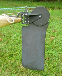
Twenty percent of blade area
is forward of the pivot
axis |
All aluminum parts are hard anodized for corrosion and abrasion
resistance. Unlike the
more colorful regular anodizing, hard anodizing leaves a two-mil
thick dark gray-green
ceramic coating that is harder than steel. It has yet to wear
through on the tip of the
rudder blade.
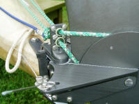
Foot or Hand Control -- and Self-Steering
The steering cables attach to the rudder yoke three inches from, and
in line with, the pivot
axis. Just inboard of each cable pin is a hole for attaching a rope
used to steer by hand or
to lash the helm. For rope steering on a regular basis (I rarely use
it), the holes should
also be on a line with the pivot axis to keep the steering rope from
slackening while
turning.
|
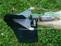
Cable steering with rope
holes for backup |
Easily Removed and Installed
When finished sailing, the rudder system can be quickly removed and
disassembled
without tools. Only the gudgeon bracket and foot pedal guides remain
fastened to the
kayak. Pulling the pintle pin releases the rudder from the gudgeon
bracket. The blade
axis pin is secured with a cotter ring, so the blade is easily
removed from the rudder
bracket. Two more cotter rings secure the steering cables to skirted
pins on the rudder
yoke. The forward ends of the steering cables have small swaged
cable stops that are fed
through Teflon tubing to the foot pedals. At the foot pedals, the
cable stops fit into
keyhole slots; no fasteners are needed. Everything is easily
removable for rinsing and
highway travel. Installation is just as easy.
|
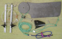
These parts are removable
without tools |
Balanced Blade
The rudder blade is balanced, with 20 percent of its wetted area
forward of the pivot axis.
For most of its length, the blade is 7-5/8 inch wide. It extends
about 14 inches below the
waterline, for a total wetted area of approximately 103 square
inches. This is 2% of the
area of the 36 square foot sail I use in light winds or about 2.5%
of my 28 square foot
sail. This is more than enough area for our kayaks.
The wetted portion of the blade is basically rectangular. The
trailing edge is straight from
the bottom up to where it curves aft to meet the pulley. Because
most of the blade is
forward of the blade axis (the "kick-up" axis, not the pivot axis),
a rectangular blade
would initially increase in depth as it swings back upon hitting a
shoal, stressing the
rudder mount. To prevent this, as well as to spread wear over more
of the blade edge, the
bottom end shape is one quadrant of an ellipse.
A Solid Stern Mounting System
Securely fastening the gudgeon bracket to the pointed stern of
the kayak was a major
challenge. It was necessary to saw one inch off the end of the kayak
to provide a flat,
vertical mounting surface of approximately 1-1/2 square inches. Two
quarter-inch
stainless tee-nuts were imbedded two inches deep in a
glass-reinforced end-pour,
perpendicular to the mounting surface. Two more tee-nuts were
imbedded in a second
pour, opening to the deck of the kayak. Quarter-inch screws and
bolts secure the bracket
to the kayak.
Every boat requires some sort of custom rudder mounting
arrangement. What makes my
design fairly adaptable is the small, but very strong, gudgeon
bracket. Because of the
kayaks' pointed sterns, I provided additional bracing to the decks.
Most boats would not
need this. When a vertical surface on the stern is not an option, a
bracket having a
vertical surface might be mounted to the stern, much the same way
ordinary gudgeons are
sometimes bolted to a hull. An advantage to this arrangement is that
the bracket could be
provided with multiple mounting-hole sets, so that mounting height
could be adjusted to
compensate for varying displacement or to fine tune the balance
between the centers of
effort and lateral resistance.
Give for Collision with Underwater Objects and
Ability to Raise or Lower the Rudder from the Cockpit
The system for absorbing impacts shares components with the system
for raising and
lowering the blade. To minimize the forces required in both systems,
I used a fairly large
diameter pulley. The blade top forms one pulley face; the other face
is formed by a disc
of aluminum, with a smaller, 5-1/4-inch disc of Plexiglas between.
A continuous loop of rope is fastened to the Plexiglas disc. This
haul loop provides a
means to hold the blade down, as well as haul it up. The forward
portion of the loop
passes through a small block adjacent to the cockpit. This block is
held by a small
adjustable loop of rope encircling the cross-tube of the BOSS rig.
The primary purpose
of this small loop is to adjust the slack in the haul loop, but by
adjusting it to its
maximum diameter, it can be slipped over the end of the cross-tube
without untying the
knot, simplifying installation and removal of the rudder system.
While sailing, the blade is held down by a length of shock cord
attached to the lower half
of the haul loop. A short length of rope is tied to the forward end
of the shock cord. This
line passes through a fairlead directly behind the cockpit, and is
secured in a cleat to the
right of the cockpit. Tension on the shock cord is adjusted
initially by sliding the knot
along the shock cord, but can be fine-tuned underway by varying the
position of the line
in the cleat. Since the working length of the shock cord is nearly
four feet, tension in the
cord increases only 8% as the rudder swings back to a horizontal
position.
|
Cleat by cockpit swivels to
align with either the shock
cord lead or haul line |
The rudder hauls up easily regardless of steering angle. Hauled
up, the rudder blade
comes to rest 20 degrees past vertical. With the shock cord
released, gravity holds the
blade in its rest position against a step cut into the blade.
However, the blade can be
secured in this position by fixing the haul loop in the cleat that
is normally used to
tension the shock cord.
Unlike some rudder designs, the rudder bracket does not
completely enclose the rudder
pulley. This allows a larger sheave diameter without a corresponding
increase in bracket
weight. It also eliminates friction between the haul rope and the
rudder bracket. By
maintaining small clearances between the bracket halves and pulley
faces I have avoided
any twisting and side-to-side slop. Teflon sheet between the pulley
faces and bracket
halves minimizes friction.
Sandwiched between the rudder bracket halves is a block of
Plexiglas that serves as the
bearing for the pintle pin. The pintle pin passes through a vertical
hole in the block.
Teflon sheet provides a bearing surface between the top and bottom
of the rudder bracket
and the gudgeons.
The most innovative feature of the rudder is the integration of
the line guide bracket and
the pintle pin. The stainless steel pintle pin is permanently
threaded into the bottom of
line guide bracket. The line guides carry the upper and lower halves
of the haul loop.
The line guides need to be located on the axis of the pintle pin.
This location prevents a
turning moment on the rudder when tension is applied to the haul
lines. It also prevents a
change in tension or slack in the haul lines as the rudder is
turned. The base of the line
guide bracket bears against a step on the upper gudgeon, keeping the
line guides oriented
fore and aft. This also prevents the pintle pin from rotating so
that there is no wear
between the stainless pintle pin and the aluminum gudgeon.
Forming the line guides bracket and pintle pin into a single
assembly has further
advantages. Tension in the haul loop holds the pintle pin in place.
The safety pin at the
tip of the pintle pin serves only as a backup. The rudder blade,
haul loop, haul loop
block, adjustable loop and the line guide/pintle pin assembly all
actually form a single
assembly, so that when removed, the various parts cannot become
separated and
misplaced.
Although the upper line of the haul loop passes straight through
its guide, the hold-down
half of the loop passes through the lower line guide at a sharp
angle. To reduce friction
and line wear, I used ceramic fishing rod line guides. Despite the
sharp angle, even slight
tension will return the rudder to vertical after passing over a
shoal. Without the need to
overcome friction in the system, shock cord tension can be minimized
to reduce wear and
the risk of damage to the blade. With well-faired holes and a good
hard-anodized
coating, it might be possible to omit the fishing rod line guides.
|
Fishing rod line guides
minimize friction |
Stop Ensures Vertical Orientation
To maintain the intended rudder balance, the blade must remain
vertical while sailing.
This is accomplished by providing a step in the forward part of the
blade under the
pulley. The Plexiglas block serves as the stop for the step so there
is no metal-to-metal
contact. Shock cord tension holds the step against the Plexiglas
block. Because the blade
axis is well aft of the blade center-of-gravity, some tension is
always required to hold the
blade against the stop.
There is no means included to adjust the stop position. My
experience with this rudder
indicates there is nothing to be gained by fine-tuning the balance
with an adjustable stop.
Mark Balogh recommended twenty percent balance, and, at least with
this design on my
boat, twenty percent seems optimal. An adjustable stop could be
included, but I don't
believe the increased complexity is justified. Slightly more pedal
pressure, or slightly
less feedback, would still be acceptable in any of the conditions I
have sailed.
Switching Blades
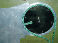
Haul loop attachment method |
The blade is easily removed but the haul rope is more or less
permanently attached to the
blade. A three-inch fold of the rope is captive in a keyhole slot
radially disposed in the
pulley's Plexiglas disk. A small plastic bead in the end of the fold
keeps the rope in the
keyhole. Six screws would have to be removed to release it. However,
since all tension
on the rope is perpendicular to the slot, it should be possible to
dispense with the keyhole
and provide a simple slot. The fold of rope could be stiffened with
resin or wire inserts to
keep it from pulling from the slot under normal use, yet it could be
pulled straight out of
the slot to change blades, with no tools required.
Stops to Limit Rudder Travel
|
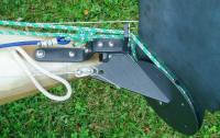
Padded rudder stop shaped
to match yoke leading edge |
Milled into the gudgeon bracket are padded stops to limit the
maximum turning angle of
the rudder. The leading edges of the rudder yoke are scalloped to
provide about 60
degrees of turning angle to either side on my kayak. This is more
than needed. I limited
the travel to about 45 degrees for my wife's kayak.
Connect Two Yokes Together when Catamaraned
The yokes of two rudders could be interconnected by providing a
set of holes in the rear
of the yoke, widening the yoke if necessary to accommodate the holes
and hardware.
Only one hole per yoke would be required if the parties involved
could agree on who was
port and starboard.
Minimal weight
Although I reduced the weight with each new version, at 4-1/2
pounds (excluding the
foot pedals), the system still seems a little heavy for a small,
lightweight kayak. There
are possibilities for further weight savings without compromising
strength or function.
These mostly involve more complex shapes or extra holes. I decided
not to take
advantage of these primarily to avoid all the extra hand sanding of
edges than cannot be
reached with my bench sander. Well-rounded edges are important
because the anodizing
won't build to the desired thickness at sharp edges.
Additional weight savings could be realized by reducing the size
of the pulley and rudder
bracket. The downside is that this would require a small increase
haul-up effort and
shock cord tension. It would also reduce the chord of the blade
slightly at its narrowest
point, just below the pulley.
For small kayaks like these, I believe the blade size could also
be reduced for a little more
weight savings without hurting sailing performance.
Field Repairs
The most likely problem underway is cable connection failure. A
spare set of cables
could be installed in just a few minutes, but it would be more
pragmatic to rely on rope
steering as a backup. If one has no extra rope, the haul loop could
be cut away and used
for a steering rope.
All screws and bolts fit into threaded holes. There are no nuts
to loosen and fall off.
Lost cotter rings could be replaced with string or a bit of copper
wire. Drilling slightly larger
holes in cable connection pins would enable the cable ends to be
bent around and used to
replace a lost cotter ring.
A lost rudder blade or pintle pin is unlikely since both are
connected to the haul lines, but
a suitable bolt could serve as a replacement pintle pin.
Carrying an extra blade axis pin would be smart. Forgetting to
attach the cotter ring,
which would be dumb, could deep-six the blade pin.
Foiled Blade Possibilities
Until reading about foiled blades in the Forum Discussion, I was
unaware of their
benefits. When sailing, I sometimes feel I loose too much momentum
during a tack.
Now I wonder how much of this loss is due to rudder drag that I
could avoid with a foiled
blade.
Another reason to consider a foiled blade might be sail plan
balance. With the standard
BOSS rig, the leeboard is immediately adjacent the mast. So, with
the leeboard vertical,
there is a lot of weather helm. However, when the rudder is lowered,
the center of lateral
resistance moves aft of the center of effort. So, theoretically (I
can't tell in practice), the
rudder needs to be angled a little to the windward to keep from
bearing-off when on a
reach. I suppose a foiled rudder would reduce the extra drag caused
by this. Possibly I
could foil the rudder by laminating foam foils to either side of the
flat blade and glassing
over them.
Home-Built at a Reasonable Cost
Except for the anodizing, I built this rudder in my basement.
Although the success of this
design is dependant upon precise dimensions and alignments, I was
able to accomplish
this using ordinary Sears shop tools, a few tricks and a lot of
forethought before each
operation.
I spared no expense obtaining the right materials for the last
rudder and probably spent as
much as I would have for a commercial rudder. But, considering the
end result, it was
worth it. Purchasing minimum order quantities over the Internet, I
spent $38 for the
aluminum. The Teflon sheet and tubing were expensive, about $40 from
my source.
Anodizing cost $30, a bargain for the value added. All the various
stainless parts, rope,
cable, line guides and Plexiglas added another $50 to $100. A
determined scrounger
could do a lot better
Plans?
What now? I have had some minor design modifications waiting in
AutoCAD for a
couple of years, but only to address weight reductions. The weights
of the current
rudders are not really a problem, and having no more kayaks, I have
no immediate plans
to build another rudder. Nonetheless, I am interested in hearing
anyone's thoughts about
the design or its suitability for other boats. I have been eyeing
those beautiful CLC kayak
kits for several years now, and I wouldn't want anything less than
the perfect rudder for a
project like that.
© Larry Miller 2005
|